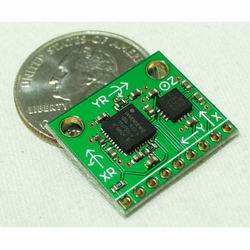
IMU
Inertial Measurement Unit (IMU)
With inertial sensors such as accelerometers and rate gyros, it is possible to obtain a more accurate picture of vehicle motion than with GPS alone. Sparkfun Electronics has a 5-DOF IMU which features a 3 axis accelerometer and a 2 axis rate gyro. Here is some information-
- Product Page
- Schematic
- Analog Devices ADXL330 3 Axis Accelerometer
- Invensense IDG-300 2 Axis Rate Gyro
Converting measured acceleration to SI metric units
The accelerometers have a nominal response of 300 mV per g. We are acquiring them through 10-bit a-d converters on the Atmel Atmega-8, with a VRef of 3.3V. Ignoring (for now) deviations, bias and noise, a straightforward conversion from the a-d integer reading N to m/s^2 is as follows:
(N-512)/1024 * 3.3V * (9.8 m/s^2)/(0.300 V/g)
or
(A) acceleration (m/s^2) = (N-512)/1024*(double)10.78;
Improved accounting will replace 512 with the measured zero-g bias. If it is possible to measure the mV/g units (which nominally vary from 270 to 330) that can also improve the accuracy, as well as taking into account a-d nonlinearities and biases unaccounted for in the zero reading.
Converting measured yaw rate to SI metric units
The yaw rate gyros have a nominal response of 2 mV per degree/second. We are acquiring them through the same a-d converters as above. So to obtain rotation in radians per second from the a-d reading N, we scale as follows:
(N-512)/1024 * 3.3V * (1 deg/s)/.002V * (Pi radians)/(180 deg)
or
rate = (N-512)/1024 * (double) 28.783;
Again, 512 can be replaced with the measured or estimated zero-rate bias. If it is possible to measure the actual voltage per degree/second (which may vary +/- 5%) that can also improve the accuracy, as well as taking into account a-d nonlinearities VRef drift, and other biases.
Possible Complimentary Sensors
Electrolytic Tilt Sensors These sensors, although they have they're own problems, were recommended by an expert on balancing robots for their low DC bias drift.
